It didn't explode....... YET (aka niges amp)

Like

Yes
22
100%
No
0
No votes
 
Total votes: 22

nige2000
Posts: 4253
Joined: Thu Feb 14, 2013 10:47 am
Location: meath

Re: It didn't explode....... YET (aka niges amp)

Post by nige2000 »

thanks guys
glad i posted pcb progress now
its as easy do it right as wrong
frd1996 wrote:Nige

Two cents from me:

* make +/-33V power tracks wider - much wider
* what is the value of R11,R12? What power do then need to dissipate?
yes brain definitely wasn't working there we will just bypass these resistors
* swap Q2 and R3
* make the output track wider
* ground plane - try to keep the hi current ground (+/-33V) separate from signal ground. That applies to decoupling caps (C2/C3)
* try to add multiple pads for decoupling caps - to try various options. As far as I can see you play to use tantalum caps. Try to add pads for electrolytics on top.
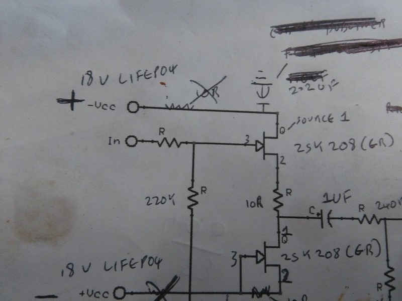
well the prototype has nearly no bypass caps, i was just leaving provision, previous experience with lifepo4 supplies suggests film bypass will be ok
* jfet buffer power pins: try to arrange them in following order: +18, GND, GND, -18, also input GND should be close to power GND.
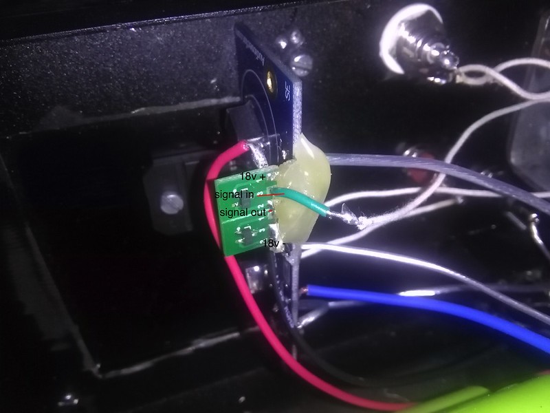
ill ask Enrico to look at the suggestions
sd card player, modded soekris dac, class a lifepo4 amp or gb class a/b amp, diy open baffle speakers based on project audio mundorf trio 10's
frd1996
Posts: 171
Joined: Sat Apr 17, 2010 10:38 am

Re: It didn't explode....... YET (aka niges amp)

Post by frd1996 »

Hi Nige,

Since yesterday I've been thinking how I would draw your PCB. I decided to try and this is what came up. This is of course the first approximation of the final layout. I am not sure if I got the schematic and j-fet packages right. If you need the source files for this (DipTrace) then please give me a shout.

F
Attachments
brd_nige.jpg
brd_nige.jpg (98.51 KiB) Viewed 338 times
nige2000
Posts: 4253
Joined: Thu Feb 14, 2013 10:47 am
Location: meath

Re: It didn't explode....... YET (aka niges amp)

Post by nige2000 »

diptrace is actually what i was trying to learn
was the only one that made any sense to me
jfet buffer pin connections looks to be incorrect i know some jfets gave different pinouts ive used 2sk208 (gr) after sound testing a bunch of jfets
see prototype
Image
Image
think the 3875 circuit look ok
Image
actually the more i think about resistors in series of lm3875 power input the more i fear it will slow the sheer speed of this amp we will likely end up shorting across
i like the routing of power and signal traces far less chance of cross contamination
maybe separate clean and dirty gnd connections to battery gnd/terminals might work better?

i see from this Peter seems to have put particular importance in a short feedback loop
Image

maybe we can put a smd resistor between pin 3 and pin 8 on the underside
Last edited by nige2000 on Sun Aug 21, 2016 3:58 pm, edited 1 time in total.
sd card player, modded soekris dac, class a lifepo4 amp or gb class a/b amp, diy open baffle speakers based on project audio mundorf trio 10's
jkeny
Posts: 2387
Joined: Sun Jan 17, 2010 9:37 pm

Re: It didn't explode....... YET (aka niges amp)

Post by jkeny »

We must all be in sync - I recently started using Diptrace too - still in 30 day trial period - it seems the best eCAD package I could find too

Why do you need a pcb package when you have a hot glue gun? :)

If the +/- 33V supplies are from batteries then you don't need the R or C which are acting as a PS filter, I believe?

Separate ground returns for signal & PS are a good idea too

Short feedback loops were said to be the essence for the success of the sound of the Gaincard & the many DIY Gainclones that arose from it
www.Ciunas.biz
For Digital Audio playback that delivers WHERE the performers are on stage but more importantly WHY they are there.
nige2000
Posts: 4253
Joined: Thu Feb 14, 2013 10:47 am
Location: meath

Re: It didn't explode....... YET (aka niges amp)

Post by nige2000 »

jkeny wrote:We must all be in sync - I recently started using Diptrace too - still in 30 day trial period - it seems the best eCAD package I could find too

Why do you need a pcb package when you have a hot glue gun? :)
just tidier, more robust and easier to assemble and we need enough of them to be feasible
If the +/- 33V supplies are from batteries then you don't need the R or C which are acting as a PS filter, I believe?
pretty much agree i will likely bypass the r, the small film cap i doubt is doing any harm, i just put them in there to be more "PC" and leave the option
in fact i didn't use the r in series between dc decoupling cap and lm3875 signal input V+ on the prototype, nor any resistors in the jfet buffer which are supposed to prevent oscillations im told
Separate ground returns for signal & PS are a good idea too
yea think we should do that
Short feedback loops were said to be the essence for the success of the sound of the Gaincard & the many DIY Gainclones that arose from it
What you think should we try to put pads for an smd r between pin 3 and 8?

frd1996 if you're happy to finish off this pcb design Enrico will move on to something else?

still looking for better/easier cheaper relays to go between the ps's and cells
what you guys think of these
http://ie.farnell.com/te-connectivity-a ... dp/1326155
Last edited by nige2000 on Sat Aug 20, 2016 5:40 pm, edited 2 times in total.
sd card player, modded soekris dac, class a lifepo4 amp or gb class a/b amp, diy open baffle speakers based on project audio mundorf trio 10's
jkeny
Posts: 2387
Joined: Sun Jan 17, 2010 9:37 pm

Re: It didn't explode....... YET (aka niges amp)

Post by jkeny »

nige2000 wrote:
jkeny wrote:We must all be in sync - I recently started using Diptrace too - still in 30 day trial period - it seems the best eCAD package I could find too

Why do you need a pcb package when you have a hot glue gun? :)
just tidier, more robust and easier to assemble and we need enough of them to be feasible
If the +/- 33V supplies are from batteries then you don't need the R or C which are acting as a PS filter, I believe?
pretty much agree i will likely bypass the r, the small film cap i doubt is doing any harm, i just put them in there to be more "PC" and leave the option
in fact i didn't use the r in series between dc decoupling cap and lm3875 signal input V+ on the prototype, nor any resistors in the jfet buffer which are supposed to prevent oscillations im told
Separate ground returns for signal & PS are a good idea too
yea think we should do that
Short feedback loops were said to be the essence for the success of the sound of the Gaincard & the many DIY Gainclones that arose from it
What you think should we try to put pads for an smd r between pin 3 and 7?

frd1996 if you're happy to finish off this pcb design Enrico will move on to something else?

still looking for better/easier cheaper relays to go between the ps's and cells
what you guys think of these
http://ie.farnell.com/te-connectivity-a ... dp/2251783
Yea, smd R would be a good idea

That's a latching relay - how are you unlatching it - reverse polarity?

This one is non-latching i.e turns off when power to coil is off http://ie.farnell.com/te-connectivity-a ... dp/1326155
www.Ciunas.biz
For Digital Audio playback that delivers WHERE the performers are on stage but more importantly WHY they are there.
nige2000
Posts: 4253
Joined: Thu Feb 14, 2013 10:47 am
Location: meath

Re: It didn't explode....... YET (aka niges amp)

Post by nige2000 »

jkeny wrote: That's a latching relay - how are you unlatching it - reverse polarity?

This one is non-latching i.e turns off when power to coil is off http://ie.farnell.com/te-connectivity-a ... dp/1326155
oops...... thats the one i meant to link
sd card player, modded soekris dac, class a lifepo4 amp or gb class a/b amp, diy open baffle speakers based on project audio mundorf trio 10's
frd1996
Posts: 171
Joined: Sat Apr 17, 2010 10:38 am

Re: It didn't explode....... YET (aka niges amp)

Post by frd1996 »

Hi,

I had some free time and worked on the amplifier board. It does not seem to be extremely difficult so I may finish it. I attach the schematic - please verify that this is correct. Few other informations:

* I verified the J-FET footprints - it matches the 2sk208 datasheet. Please double check it. The dot indicates the source pin.
* I removed R-C power filters. Instead I added footprints for small SMD caps - fully optional to install.
* _All_ capacitors and _all_ resistors are SMD 1206.
* The board got smaller 4x4 [cm].
* I will probably add vias between top and bottom GND copper pours.

Questions:

* What is the story with C1 (this is in the signal path). What type/size of capacitor do you anticipate there?
* Do you need any mounting holes, i.e. how the board will be mounted?
* Do you expect to use any connectors to connect the power/signal to the board, or all wires will be soldered?
Attachments
Schematic
Schematic
nige_sch1.jpg (48.04 KiB) Viewed 235 times
frd1996
Posts: 171
Joined: Sat Apr 17, 2010 10:38 am

Re: It didn't explode....... YET (aka niges amp)

Post by frd1996 »

The pictures of the board.
Attachments
Bottom layer
Bottom layer
nige_pcb1_bottom.jpg (41.23 KiB) Viewed 233 times
Top layer
Top layer
nige_pcb1_top.jpg (71.53 KiB) Viewed 233 times
All layers
All layers
nige_pcb1_all.jpg (72.77 KiB) Viewed 233 times
nige2000
Posts: 4253
Joined: Thu Feb 14, 2013 10:47 am
Location: meath

Re: It didn't explode....... YET (aka niges amp)

Post by nige2000 »

frd1996 wrote:Hi,

I had some free time and worked on the amplifier board. It does not seem to be extremely difficult so I may finish it. I attach the schematic - please verify that this is correct. Few other informations:

* I verified the J-FET footprints - it matches the 2sk208 datasheet. Please double check it. The dot indicates the source pin.
think its ok i must have misread it first time
* I removed R-C power filters. Instead I added footprints for small SMD caps - fully optional to install.
* _All_ capacitors and _all_ resistors are SMD 1206.
* The board got smaller 4x4 [cm].
* I will probably add vias between top and bottom GND copper pours.

Questions:

* What is the story with C1 (this is in the signal path). What type/size of capacitor do you anticipate there?
1210
* Do you need any mounting holes, i.e. how the board will be mounted?
would it not be ok to suspend it from the lm3875 chip
* Do you expect to use any connectors to connect the power/signal to the board, or all wires will be soldered?
probably just soldered

can you email me the diptrace files, maybe it will help me learn how to use it
sd card player, modded soekris dac, class a lifepo4 amp or gb class a/b amp, diy open baffle speakers based on project audio mundorf trio 10's
Post Reply