OK, I think finished the layout. Nige, I sent you the DipTrace source files. Please let me know if you need anything else.
Cheers,
F
It didn't explode....... YET (aka niges amp)
Re: It didn't explode....... YET (aka niges amp)
- Attachments
-
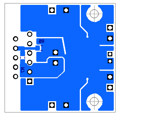
- nige_pcb2_all.jpg (105.57 KiB) Viewed 255 times

Re: It didn't explode....... YET (aka niges amp)
Great work guys. I was going to chip in earlier and suggest keeping the mounting holes if it made no odds - and I see you have. They're handy sometimes....
fran
fran
Do or do not, there is no try
Re: It didn't explode....... YET (aka niges amp)
Some suggestions :
- keep PS grounds together & signal grounds together (input & output)
- join them together by a narrow trace or wire
So input ground runs to output ground with wide trace splitting the PS grounds into two islands - join the two PS ground islands by a thick wire or braid. Join the I/O ground to PS ground by thin wire
The idea here is that the stronger & probably dirtier circulating currents of the PS don't pollute the more subtle/cleaner circulating currents of I/O. There may be no audible difference in doing this Vs using one solid ground plane but if it's easy enough to implement there's no harm in doing it.
- I would also try to include some bypass caps close to the LM3875s V+/V- pins - maybe run the ground plane up around these pins
Also, one question - I'm not sure what the purpose of the splits in the ground plane around the +/-18V pads? I would leave them out - it may make the ground return currents take a more circuitous route?
Last edited by jkeny on Tue Aug 23, 2016 12:19 am, edited 1 time in total.
www.Ciunas.biz
For Digital Audio playback that delivers WHERE the performers are on stage but more importantly WHY they are there.
For Digital Audio playback that delivers WHERE the performers are on stage but more importantly WHY they are there.
Re: It didn't explode....... YET (aka niges amp)
we were thinkin as the jfet buffer and lm3875 does not need a gnd connection perse just v+ and v- the battery terminal 0v will be star gnd for all (incl speaker) returns having multiple gnd connections to the amp board has the possibility of a gnd loopjkeny wrote:Some suggestions :
- keep PS grounds together & signal grounds together (input & output)
- join them together by a narrow trace or wire
i think i see a couple of vias between all gnds on the diptrace files
batteries are pretty forgiving might all have no effect
sd card player, modded soekris dac, class a lifepo4 amp or gb class a/b amp, diy open baffle speakers based on project audio mundorf trio 10's
Re: It didn't explode....... YET (aka niges amp)
Is the blue colour in the above diagrams the bottom copper plane of a 2 layer board - mostly taken up by a ground plane?nige2000 wrote:we were thinkin as the jfet buffer and lm3875 does not need a gnd connection perse just v+ and v- the battery terminal 0v will be star gnd for all (incl speaker) returns having multiple gnd connections to the amp board has the possibility of a gnd loopjkeny wrote:Some suggestions :
- keep PS grounds together & signal grounds together (input & output)
- join them together by a narrow trace or wire
i think i see a couple of vias between all gnds on the diptrace files
batteries are pretty forgiving might all have no effect
LM3875 is a dual supply device but that just means that both supplies return currents to ground.
The datasheet has a section called "LAYOUT, GROUND LOOPS AND STABILITY"
When designing a layout, it is important to return the load ground, the output compensation ground, and the low
level (feedback and input) grounds to the circuit board common ground point through separate paths. Otherwise,
large currents flowing along a ground conductor will generate voltages on the conductor which can effectively act
as signals at the input, resulting in high frequency oscillation or excessive distortion. It is advisable to keep the
output compensation components and the 0.1 μF supply decoupling capacitors as close as possible to the
LM3875 to reduce the effects of PCB trace resistance and inductance. For the same reason, the ground return
paths should be as short as possible.
Just my suggestions if you are designing a pcb!
Yes, it may not be important with battery supply but I would still try to follow these guidelines
www.Ciunas.biz
For Digital Audio playback that delivers WHERE the performers are on stage but more importantly WHY they are there.
For Digital Audio playback that delivers WHERE the performers are on stage but more importantly WHY they are there.
Re: It didn't explode....... YET (aka niges amp)
how is that possible there is no gnd pin on the lm3875 the only return surely for v+ can be v- and visa versajkeny wrote:Is the blue colour in the above diagrams the bottom copper plane of a 2 layer board - mostly taken up by a ground plane?nige2000 wrote:we were thinkin as the jfet buffer and lm3875 does not need a gnd connection perse just v+ and v- the battery terminal 0v will be star gnd for all (incl speaker) returns having multiple gnd connections to the amp board has the possibility of a gnd loopjkeny wrote:Some suggestions :
- keep PS grounds together & signal grounds together (input & output)
- join them together by a narrow trace or wire
i think i see a couple of vias between all gnds on the diptrace files
batteries are pretty forgiving might all have no effect
LM3875 is a dual supply device but that just means that both supplies return currents to ground.
i thought ground 0v as been kinda virtual and just the midpoint between v+ and v-
meaning that the whole pcb gnd is only signal gnd as lm3875 v+ and v- are handling the returns
unless the filter caps are installed im not sure how much contamination that would cause?
keep em coming :)The datasheet has a section called "LAYOUT, GROUND LOOPS AND STABILITY"When designing a layout, it is important to return the load ground, the output compensation ground, and the low
level (feedback and input) grounds to the circuit board common ground point through separate paths. Otherwise,
large currents flowing along a ground conductor will generate voltages on the conductor which can effectively act
as signals at the input, resulting in high frequency oscillation or excessive distortion. It is advisable to keep the
output compensation components and the 0.1 μF supply decoupling capacitors as close as possible to the
LM3875 to reduce the effects of PCB trace resistance and inductance. For the same reason, the ground return
paths should be as short as possible.
Just my suggestions if you are designing a pcb!
i think i see what your on about in this picYes, it may not be important with battery supply but I would still try to follow these guidelines
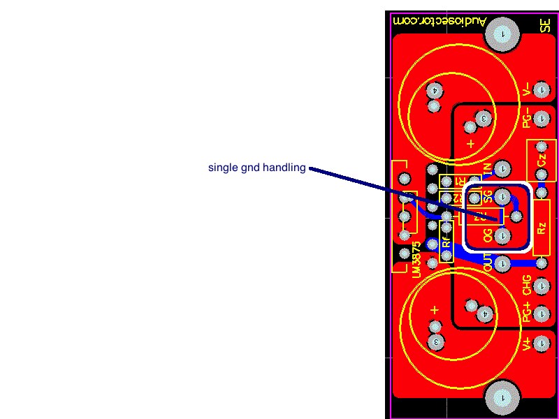
as far as i can make out these light traces is signal gnd, input and output gnd are very close connected with a short light trace and then output gnd is lightly connected to the large pcb gnd
sd card player, modded soekris dac, class a lifepo4 amp or gb class a/b amp, diy open baffle speakers based on project audio mundorf trio 10's
Re: It didn't explode....... YET (aka niges amp)
Yes, Peter's pcb shows +/- power ground connections (PG+ & PG-) which the coupling caps are connected to (I still think you should provide provision for coupling caps) & signal I/O grounds which are on the same ground plane. It's a clever arrangement because the PS return currents will take the lowest resistance/impedance return path back to the supply & therefore these currents will remain closely tucked tightly into both edges of the ground plane, therefore not contaminating the signal grounds in the centre. (the blue lines on Peter's pcb are the signal traces on the bottom plane, I believe?)
In your pcb I would move the +/- 18V pads to the corners, further away from input pads (I presume the splits in the ground plane between 33V & 18V are to provide some isolation between these PSes?) - again this will tend to keep any PS current returns away from Input current ground returns. But if you are doing this why not just make the output ground & input ground into a single wide trace running up the centre of the board & connect it to the PS grounds by light traces on either side - it's a belt & braces way of ensuring no stray PS currents pollute the signal currents?
Edit: Nige - you can't provide +33V without having a ground return to your battery pack. Similar with -33V, +18v -18V - they all need returns to battery to complete the circuit. All these returns need to be connected at one ground point i.e they are not floating, otherwise you will get ground loop hum problems.
www.Ciunas.biz
For Digital Audio playback that delivers WHERE the performers are on stage but more importantly WHY they are there.
For Digital Audio playback that delivers WHERE the performers are on stage but more importantly WHY they are there.
Re: It didn't explode....... YET (aka niges amp)
what about if gnd1 and gnd2 were moved into left side corners and c2 and c3 were placed as close to lm3875 v+/v- pins as possible
move signal gnd in beside signal gnd out and make it more like an island with a moat and a narrow bridge for "peaceful travellers"
move signal gnd in beside signal gnd out and make it more like an island with a moat and a narrow bridge for "peaceful travellers"
sd card player, modded soekris dac, class a lifepo4 amp or gb class a/b amp, diy open baffle speakers based on project audio mundorf trio 10's
Re: It didn't explode....... YET (aka niges amp)
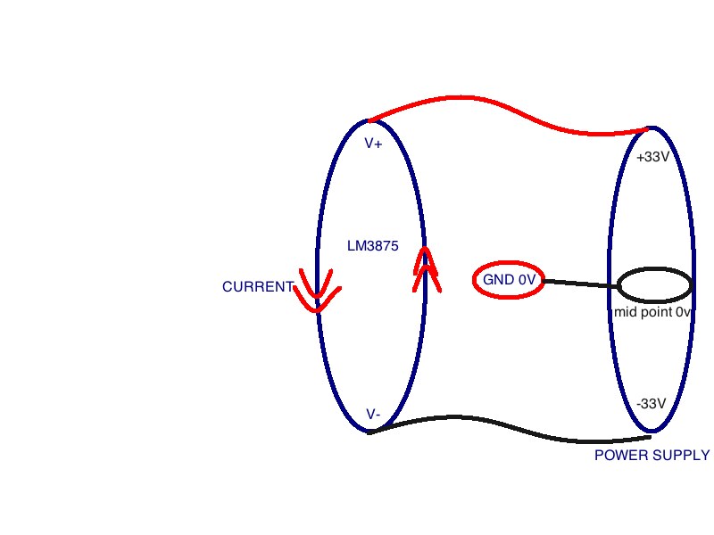
but -33 is the return for +33 that is circuit completedjkeny wrote: Edit: Nige - you can't provide +33V without having a ground return to your battery pack. Similar with -33V, +18v -18V - they all need returns to battery to complete the circuit. All these returns need to be connected at one ground point i.e they are not floating, otherwise you will get ground loop hum problems.
its same as using a single supply 0-66v and we use +33 (midpoint) as our gnd point at cell 0v which is connected to lm3875 pcb gnd and speaker return and chassis gnd
oh.... the battery pack is one unit 0 - 66v not two 0-33v
if you connect to any two voltages on the 20 voltage rails thats a completed circuit
sd card player, modded soekris dac, class a lifepo4 amp or gb class a/b amp, diy open baffle speakers based on project audio mundorf trio 10's
Re: It didn't explode....... YET (aka niges amp)
I'm not sure of your battery arrangements - if you are using multiple batteries in a pack & taking the midpoint as ground then that mid-point/ground is where your PS currents return to from both +33V & -33V supply - the +33V currents don't return to the -33V. If you are using one 66V battery& creating a virtual ground then that is the return point, I believe.nige2000 wrote:but -33 is the return for +33 that is circuit completedjkeny wrote: Edit: Nige - you can't provide +33V without having a ground return to your battery pack. Similar with -33V, +18v -18V - they all need returns to battery to complete the circuit. All these returns need to be connected at one ground point i.e they are not floating, otherwise you will get ground loop hum problems.
its same as using a single supply 0-66v and we use +33 (midpoint) as our gnd point at cell 0v which is connected to lm3875 pcb gnd and speaker return and chassis gnd
oh.... the battery pack is one unit 0 - 66v not two 0-33v
if you connect to any two voltages on the 20 voltage rails thats a completed circuit
www.Ciunas.biz
For Digital Audio playback that delivers WHERE the performers are on stage but more importantly WHY they are there.
For Digital Audio playback that delivers WHERE the performers are on stage but more importantly WHY they are there.